How to make a water turbine generator project-Flow measurement
There are many Flow measurement methods, water consumption is generally very small for micro water turbine generator station with high head and tiny flow rate of the unit to generate electricity.
here teach you the container measurement to know how much flow your project can get, the method is simple, easy to operate.
Tools: a bucket or a calculated water container, a watch (stopwatch is the best one), notebooks and pens.
Operation:
1 First determine how many kilograms of water bucket can be used, (a kilogram of water volume=0.001cubic meter=1liter), water should be balance with barrel mouth, data should be accurate.
2 Water will flow by an outlet like a tube into the bucket container.
3 Use the bucket container to catch the water from the outlet, use watch to take the time, look at how many seconds after a bucket full with water, repeated three times, take the average data.
4, calculation flow formula: flow (l/s) = a bucket of water heavy (liters)/pick up a bucket of water time (average per second).
Example: one is 20 kilograms of bucket, 5 seconds after filled with water. Flow = 20 kg / 5 seconds = 4 kg/SEC.=4 l/s.
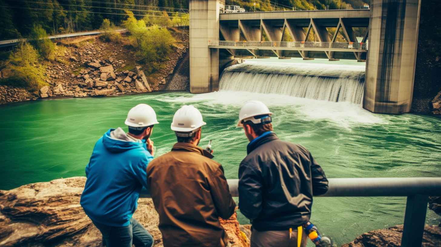
Channel flow measurement is suitable for some large water flow micro hydropower plant.
Use the buoy to measure the water flow volume.
The most simple measuring method on small rivers, are generally adopts the buoy measured velocity, according to the water flowing area (or the river bed cross sectional area), to calculate the river flow; because the flow rate is equal to the velocity of water flow multiply the water flowing area. Use of buoy method of measuring flow steps are as follows:
(1) Choose a relatively flat water channel section, as shown in the (figure below) requires its breadth and depth of the drainage channels are not changes too much, channel length for 10 meters. (The longer the length calculation more accurate)
(2) On the selected channel section arrangement of two sections, with a stakes Mark two points in the upstream with “A”, and in downstream with “B” of the channel, and then measure the breadth and depth of the channel between the two sections; prepare a float (such as leaves or a wood) and a clock, then use the clock to count how many seconds the float will take to flow from A to B.
(3) Supposing that, the length, width and height in the cross-section of point A are 10m, 50cm and 40cm separately. And the float takes 8 seconds to flow from A to B.
A’s sectional area is: 10m×0.5m×0.4m=2m3=2000liters/second. (Tip: 1 m3=1000liters)
The Water flow will be: 2m3÷8=0.25m3/second=250liters/second.
(4) Rectangular channel area = channel width by the depth of the water
Trapezoidal area = (surface width + canal bottom width) ÷ 2 x the depth of the water
After this 3 ~ 5 times measurement, it is concluded the average time (in seconds) that float flow between two sections of the channel. With an average time in addition to the length between the two sections, you can get more accurate data.